Quality Assurance
Circuit board assembly is our specialty, along with cable and wire harness. The concept of Printed Circuit Board Assemply ("PCBA") may be simple: populating (placing and soldering) electronic components onto a circuit board as designed; the resulted quality of electronic assembly, however, can be different from manufacturer to manufacturer, depending on manufacturing techniques, workers skills, and quality assurance system in place.
Circuit board, or Printed Circuit Board ("PCB"), is a substrate ("support", in layman term; normally glass-epoxy material) with copper forming on surfaces, inner layers (for multi-layer board), and holes between layers. These copper formings serve as pads for components' leads to sit on and be soldered, and as paths and traces for  components, as well as layers, to connect each other.
All electronic componenets can be grouped into two categories, i.e., THT and SMT. THT or Thru-hole stands for Through Hole Technology, while SMT Surface Mount Technology. The basic difference of these two is that THT components are those with leads coming through the circuit board, while SMT mounting on the surface of the board. The significance of SMT technology, however, is that it has revolutionized the electronic industry; simply put, it makes automation of assembling possible. In other words, while THT relies on traditional wave soldering and hand soldering techniques, SMT uses highly automated processing equipment for assembling so is more efficient and consistent in quality assurrance.
It is worth to mention that electronic, especially semiconductor, technology advances rapidly, resulting in components with higher and higher speed, smaller and smaller size, more and more functional, all of which, unfortunately, means more and more difficult in manufacturing. BGA (ball grid array) packages, for example, not only have many leads densely designed, but the mounting is required underneath the package. More sophisticated Equipment, higher accuracy, speed, and skills are required for this type of jobs. Building on years of experience, including continuous technology improving, GIC has established a capacity in meeting most of customer requirements.
Our Quality Management System
GIC has established a Quality Management System which meets ISO 9001:2015 quality management standard and practice, including well-defined Quality Policy, Quality Objectives, and Plan for continual improvement. Upon request, a copy of Quality Manual can be provided to customer.
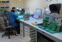
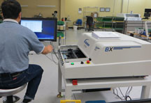
As for quality control, all of our products will go through several inspection check posts during production and are 100% inspected at the final inspection.
Our quality control process actually begins much earlier. Right after receiving customer POM or drawings, we first layout a process flow plan, which will include inspection check points, means, and cover areas such as materials, soldering, touch-up, visual check, optical, microscope, X-ray inspection, and final testing.
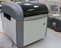 Using a solder screen, called stencil, and a runner (squeegee, or roller) moving across the screen, solder paste is squeened and deposited directly onto the board and registered in the correct positions. As the screen of stencil is generated from the printed circuit board files, it has holes on the positions of the solder pads, and in this way solder is deposited only on the solder pads.
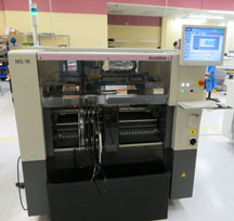
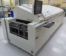 treatment, namely a four-stage thermal profiling (pre-heat, soak, reflow, and peak), each stage would require a combination of specific time and temperature depending on the nature of PCB board and solder paste used. We use the state of the-art KIC Explorer Profiler to help optimization therefore ensure soldering quality.
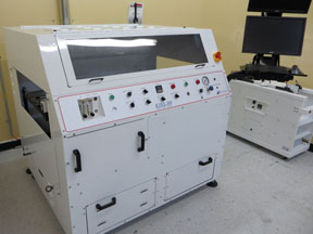
 other high-pitch components, X-ray inspection may be applied.